JTAG Debugging Setup For Beaglebone Black
The original Beagleboard (white) has a JTAG emulator built in, which we can access through the usb port we use to power the board. But the Beaglebone Black (BBB) doesn’t have that feature, instead it has a JTAG Connector pad in the back of the board where we can connect an external JTAG debugger/emulator.
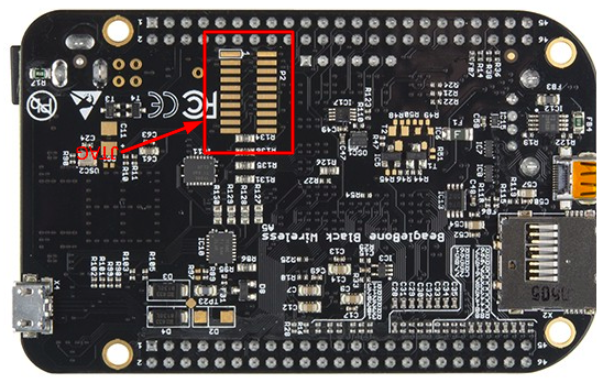
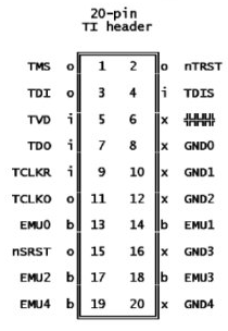
The pads are numbered 1 at the top left then 2 top right, 3 is second top on the left, 4 is second top to the right, then the pin number increments as you move left then right down the pads. Note that the pin 6 is keyed.
Let me share what I learned while setting up a JTAG debugging setup for Beaglebone Black.
For the debugging setup we need to select,
- a Header pin
- a JTAG Emulator/Debugger
- an adapter (if required)
Header Pin
The Beaglebone Black has a CTI20 JTAG Connector pin layout. You can refer more about different types of JTAG connectors here. We have to solder the header to the board ourselves as it originally doesn’t come with a header.
The header should have, 2 rows of 10 pins each, with the dimentions,
- 0.05” (1.27mm) pin pitch
- 0.10” (2.54mm) row pitch.
Some suggested headers I found on the internet are,
- FTR-110-03-G-D-06
- FTR-110-01-T-D
- FTR-110-51-L-D-06
These headers are manufacutured by Samtec. There are other manufacturers as well. The part numbers will differ. I couldn’t find these pins in my local stores. So I ordered them online. I went with the option (1).
First we’ll understand what these numbers mean.
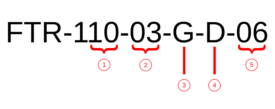
| No | Description | FTR-110-03-G-D-06 | FTR-110-01-T-D |
|---|---|---|---|
| 1 | Number of pins per row | 10 | 10 |
| 2 | Pin length code (datasheet) | 3.18 mm | 5.84 mm |
| 3 | Plating type | Gold | Tin |
| 4 | Number of rows | Double row | Double row |
| 5 | Other features | 6th pin is keyed(absent) | - |
Take a look at the datasheet for detailed descriptions.
In the second option, we should manually remove the 6th pin. Also the pins are a bit long. It shouldn’t be a problem.
As I didn’t have much soldering experience, I didn’t wanted to solder it myself because I could accidentally damage the board. I got it soldered from a local mobile phone repairing shop as they have experience in soldering similar stuffs.
Emulator
BBB has a TI Sitara AM335x SoC which is based on a single ARM Cortex-A8 core. When selecting a JTAG Emulator check whether the emulator supports the chip/processor. If your emulator doesn’t have a CTI20 connector, you’ll need an adapter. I came accross the following JTAG Emulator options.
- Segger J-Link Edu (Not Edu Mini) + TI-CTI-20 Adapter
- TMDSEMU110-U
- Blackhawk XDS100v2D
I chose the Segger J-Link Edu. It has a standard ARM20 JTAG connector. So I had to buy an ARM20 to CTI20 adapter as well.
You’ll need a USB-to-TTL Converter to observe the serial console output of the board. Other than that, it’s better if you can find some plastic screws or spacers to mount the board.
My order: JTAG Emulator | Adapter | CTI20 Header